Grover's search - Part 4
Interactive circuit visualization using Circuit Designer widget
In previous parts of this tutorial, we have shown how to draw a circuit diagram for a program represented by a QPU object using its draw() method. Diagrams generated in this way are static, and can become quite large for longer programs, which limits their usefulness. In this part of the tutorial, we are going to show you how to leverage PsiQDK's integration with Circuit Designer to create interactive circuit diagrams.
1. Prerequisites
We will visualize the program we discussed in Part 2 of the tutorial. We reintroduce the necessary Qubricks and built the program in the cell below. Note that unlike in previous parts, here we don't use the top-level GroversSearchSATProblem Qubrick, and for simplicity we run only one solution attempt.
from psiqdk.workbench import Qubrick, Qubits, QPU
class EvaluateClause(Qubrick):
"Qubrick that evaluates one SAT clause"
def _compute(self, x: Qubits, y: Qubits, literals: list[tuple[int, bool]]) -> None:
# Build a mask of control qubits for this clause
ind, pos = literals[0]
controls = x[ind] if pos else ~x[ind]
for ind, pos in literals[1:]:
controls |= x[ind] if pos else ~x[ind]
# Calculate OR of the literals in the clause
y.x(cond=~controls)
y.x()
class EvaluateFormula(Qubrick):
"Qubrick that evaluates a SAT formula"
def _compute(
self, x: Qubits, y: Qubits, clauses: list[list[tuple[int, bool]]]
) -> None:
num_clauses = len(clauses)
# Allocate auxiliary qubits for clause evaluation
a = self.alloc_temp_qreg(num_clauses, "a", release_after_compute=True)
clause_evaluator = EvaluateClause()
# Evaluate clauses and store results in corresponding auxiliary qubits
for ind, clause in enumerate(clauses):
clause_evaluator.compute(x, a[ind], clause)
# Evaluate the formula as the AND of auxiliary qubits
y.x(cond=a)
# Uncompute clauses evaluation
for _ in range(num_clauses):
clause_evaluator.uncompute()
class PhaseKickbackPrep(Qubrick):
"""Qubrick to prepare an auxiliary qubit in |->."""
def _compute(self, register: Qubits):
register.x()
register.had()
class MeanStatePrep(Qubrick):
"""Qubrick to prepare the mean state on our input register."""
def _compute(self, register: Qubits):
register.had()
class ReflectionAboutTheMean(Qubrick):
"""Qubrick to perform reflection about the mean."""
def _compute(self, register: Qubits, mean_state_preparation_qbk: MeanStatePrep):
mean_state_preparation_qbk.compute(register, dagger=True)
(~register).reflect()
mean_state_preparation_qbk.compute(register)
num_inputs = 2
# Clause: (x₀) ∧ (¬x₁)
clauses = [[(0, True)], [(1, False)]]
qpu = QPU(num_qubits=num_inputs + len(clauses) + 1)
x = Qubits(num_inputs, "x", qpu)
minus = Qubits(1, "|-⟩", qpu)
oracle = EvaluateFormula()
reflection_about_the_mean = ReflectionAboutTheMean()
mean_state_preparation = MeanStatePrep()
mean_state_preparation.compute(x)
PhaseKickbackPrep().compute(minus)
# Oracle call
oracle.compute(x, minus, clauses)
# Reflection about the mean
reflection_about_the_mean.compute(x, mean_state_preparation)
# Measure
result = x.read()
2. Drawing interactive circuit diagrams
Drawing interactive circuit diagrams can be achieved in two simple steps:
- Import the
circuit_designermodule frompsiqdk.workbench.integrationspackage. - Call
circuit_designer.drawand pass it yourQPUinstance.
from psiqdk.workbench.integrations import circuit_designer
circuit_designer.draw(qpu)
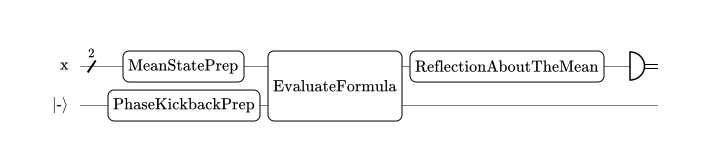
As already mentioned, the graph drawn about is interactive. Clicking any Qubrick or register will toggle it between collapsed and expanded state.
The default collapsed/expanded state of objects on the graph can be controlled by passing expanded parameter to the draw function. It accepts the following values:
False(default): Nothing is expanded.True: Both Qubricks and registers are expanded."registers": Registers are expanded, Qubricks are collapsed."qubricks": Qubricks are expanded, registers are collapsed.
For instance, this is how the diagram looks if we only expand Qubricks, but keep registers collapsed:
circuit_designer.draw(qpu, expanded="qubricks")

It is also possible to limit the depth of the drawing by passing an integer to the depth keyword argument, in which case no details will be present for routines deeper than depth in the call stack. For example, this is how the diagram looks like with depth=2:
circuit_designer.draw(qpu, depth=2, expanded=True)
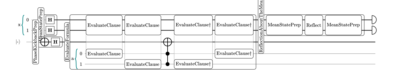
Note that this is different than just collapsing Qubricks at given level. In a diagram with restricted depth, the deepest Qubricks cannot be expanded, as the data is not present in the diagram. Using depth is especially useful for larger programs, for which drawing the full diagram would be infeasible due to performance limitations.
3. Exporting for use with Circuit Designer tool
Circuit Designer ⧉ widgets might be insufficient if one wants to tweak the aesthetics of the diagram or otherwise modify it. In such cases, it is possible to export the circuit to a JSON file that can be used in Circuit Designer tool.
To export program to a file, you can use export function from circuit_designer module, and pass it a QPU instance, and a file name (or a path). If the file name does not end with an extension, the ".circuit" suffix will be added. The function always returns the exported data as native Python dictionary, but for the purpose of this tutorial we will ignore the return value.
# Save as grover_search.circuit
_ = circuit_designer.export(qpu, "grover_search")
The export function accepts the same keyword arguments as draw, so its possible to choose which objects are being expanded, and to control the depth of the export, e.g.:
_ = circuit_designer.export(qpu, "grover_search", depth=2, expanded="qubricks")